AirGuard RGT Series

ІъЖ·ГыіЖЈәAirGuard RGT Series
ІъЖ·ұаәЕЈә113157-463
ІъЖ·РНәЕЈәRF51062*,RF51063*,RF51064*,RF51065*,RF51066*,RF51067*,RF51Ўӯ
ёьРВКұјдЈә2009.12.03
іцЖ·і§јТЈәУў№ъMTLАЛУҝ·ААЧұЈ»ӨЖч
дҜААҙОКэЈә37

AirGuard RGT Series
Maximum discharge current
20kA (8/20ҰМs)
Maximum power rating (VSWR)
1.25:1
Frequency Range
DC to 4.0GHz
Peak Pulse Current (8/20ms)
40kA
Impedance
50 or 75 Ұё
(depending on connector type)
| Model | Connectors | Frequency Range (GHz) |
VSWR | Insertion Loss (dB) |
Peak Pulse Current (8ҰМs x 20ҰМs) |
Impedance (Ұё) |
| RF51062* | 7/16 Bulkhead(f) to 7/16(m) | DC - 4.0 | 1.25:1 | 0.1 | 40kA | 50 |
| RF51063* | 7/16 Bulkhead(f) to 7/16(f) | DC - 2.5 | 1.25:1 | 0.1 | 40kA | 50 |
| RF51064* | N Bulkhead(f) to N(f) | DC - 2.5 | 1.25:1 | 0.1 | 40kA | 50 |
| RF51065* | BNC Bulkhead(f) to BNC(f) | DC - 2.5 | 1.25:1 | 0.1 | 40kA | 50 |
| RF51066* | TNC Bulkhead(f) to TNC(f) | DC - 2.5 | 1.25:1 | 0.2 | 40kA | 50 |
| RF51067* | TNC(m) to TNC(f) | DC - 2.5 | 1.25:1 | 0.2 | 40kA | 50 |
*Add alpha suffi x to identify gas-tube voltage: A = 90V, B = 145V, C = 230V, D = 350V, E = 470V, F = 600V, G = 800V, H = 1,000V
Gas-Tube Voltage (Voltage should be defi ned by maximum RF power)
| Parameter | Gas-Tube Voltage | |||||||
| Voltage Code | A | B | C | D | E | F | G | H |
| Gas-Tube Voltage Rating | 90 | 145 | 230 | 350 | 470 | 600 | 800 | 1000 |
| Maximum RF Watts See notes 1, 2, 3 | 37 | 96 | 241 | 558 | 1006 | 1640 | 2915 | 4555 |
| kA Transient Current for 8 x 20ҰМs pulse | 40 | 40 | 40 | 40 | 40 | 40 | 30 | 20 |
| V dynamic at 5k/ҰМs | 600 | 600 | 650 | 800 | 1200 | 1500 | 1900 | 2200 |
| Let-through Energy in mJ see notes 1 & 4 | 0.3 | 0.3 | 0.35 | 0.7 | 2.2 | 4.4 | 9 | 14 |
Note 1: Data given for 50Ұё systems. For 75Ұё systems multiply by 0.67, for 90Ұё systems multiply by 0.55.
Note 2: For combined carrier applications the sum of all peak RF voltages plus any injection voltages should not exceed 60% of the Gas-Tube voltage rating. Peak RF volts = 1.4 x (RF power x Ohms) ^0.5.
Note 3: RF power is limited by the connector capability also.
Note 4: Let-through Energy based on the 6kV/3kA per ANSI C62.41.
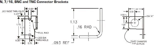
Brackets
| Model | Connectors | Diameter |
| RF51074 | 7/16 DIN | 1.146Ўұ ( 2.91cm) |
| RF51075 | N | 0.630Ўұ (1.6cm) |
| RF51077 | BNC/TNC | 0.505Ўұ (1.28cm) |