SCHIRTEC-A E.S.E. LIGHTNING CONDUCTOR

Product Name:SCHIRTEC-A E.S.E. LIGHTNING CONDUCTOR
Product Model:Schirtec-A
Updated:2010.03.29
Views:2

SCHIRTEC E.S.E. LIGHTNING CONDUCTORS
The main function of the lightning protection system installed on the existing building is to capture a lightning stroke and then conduct discharge current safety to the ground.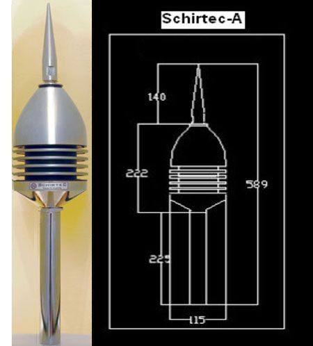 In some conditions, however the active lightning system is the only possible method to protect from direct lightning strokes. Due to the arguments mentioned above, we recommend to use the active lightning protection whenever the conventional solution is inconvenient or when the former is more preferable to the latter as in the case of the efficient protection of architect.
A lightning discharge is initiated by so-called leader which drifting downwards or upwards creates the ionised air path between cloud and ground for a lightning current to flow. This is the main lightning discharge characterized by its visual and sound effects; bright flash and thunder sound, when the electric field value suddenly increases as a result of potential difference between the ground and the clouds..
Schirtec-A lightning conductor is formed by two armatures. One of them is connected to ground, while the other remains at atmospheric potential. The great magnitude of the electric field during the thunderstorm produces that, although armatures are separated by a very short distance, the difference of potential between them during lightning approaching becomes considerable.
This difference of potential is the power supply of the lightning conductor internal device. The internal device is located in the body of Schirtec-A and is called Variable Impedance Unit. Therefore, the device working is regulated by the atmospheric field. The advantages of these characteristics are, on one side, that in normal conditions the device is not working, avoiding then unnecessary stress to the components. On another side, during thunderstorms the device detects when a proper electric field exists, and when the downward leader is approaching, because it provokes a strong and rapid increase of the atmospheric electric field.
During normal atmospheric conditions, the charge is also neutral in every area (also at the air), and the internal device is not working.
The first difference with a simple lightning rod starts already when storm clouds appear. Inside the components of the internal device, equi-potential lines become very close together, causing the necessity of a strong concentration of charges at the armature surface. The device is designed in such a way that the transitory current does not get lost, but remains as electromagnetic fields in the components of the electrical device. The electric field value, able to ionise the air around the tip, is reached earlier than with a simple rod, because the internal device makes the voltage increase over ground level. Then, air charges become also a part of the internal current. Therefore, the ionised area is growing much faster than with a simple rod.
The previous phase to the formation of the upward leader is the formation of corona discharges (streamers) that propagate towards the downward leader. One of these streamers will become the upward leader, which will propagate continuously to the downward leader, forming then the lightning discharge path.
Inside the lightning conductor, the downward leader approaching and the strong increase of the electric field caused by it are the factors that activate the mean function of the internal device .When the voltage between the armatures exceeds a certain value which the circuit is designed for, then the internal trigger works, using the accumulated energy for pumping to inside the ionised area. The strong and sudden concentration of positive charges cause repellent forces in the ionised area, which break the existing border. The device has provoked then a streamer effect, avoiding the glow regime that was lowering the effectiveness of a simple lightning rod.
The streamer emission under these conditions favours the upward leader formation, which will progress continuously till reaching the downward leader, forming then the discharge path. Then, as the Schirtec-A is the point where the upward leader was formed. It will be the receiver of the lightning strike.
Installation:
Schirtec-A should be installed 2 meters higher up than the highest point of the protected structure. The protection level is depended on the height at which air terminal is installed and on its power and min.3 meters from medium and high voltage installations. It should be connected with down conductors lying on opposite structure walls.
|
DOWN CONDUCTORS | |
|
Material |
Minimum Dimensions |
| Bare or tin-plated Electrolytic Copper | Strip 30 x 2 mm Round Section : 8 mm dia Braided cable 30 x 3,5 mm |
| 18 / 10-304 Stainless Steel | Strip 30 x 2 mm Round Section : 8 mm dia |
| A 5/L Aluminium | Strip 30 x 3 mm Round Section : 10 mm dia |
It is required an earth resistance less than 10 ohm.
A Lightning Strike Counter can be installed at the down conductor to count the flows of the lightning current.
Schirtec E.S.E. Features:
*possibility of protection of large and complex structures through only one point with the active air terminal installed on the top which makes the system easy to install.
*device completely ecological and non-radioactive
*no outside power source, device completely autonomous
*weather-proof device
*no moving parts
*dynamic response to the approach of a lightning downward leader
|
SCHIRTEC-A E.S.E. LIGHTNING CONDUCTOR | ||||||
|
Ref. |
Description |
ΔT:Acc. to NFC 17-102 |
Test Report of SCHIRTEC-A |
Material |
Size (cm) |
Weight (kg) |
|
S-A |
E.S.E. Type Lightning Rod ΔT:60µs |
60µs |
68µs |
Stainless Steel |
59x12 |
App. 2.8 |
Notes: Schirtec-A is testable with the external test device (SA-1T TESTER).
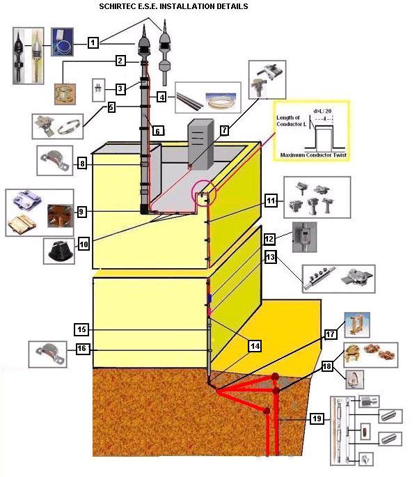
1.SCHIRTEC-A,SCHIRTEC-DA AND SCHIRTEC TESTER
2.CONDUCTOR COUPLING
3.MAST ADAPTER
4.DOWN CONDUCTOR
5.MAST CLIP
6.GALVANIZED MAST (2 or according to customer is demand)
7.MECHANICAL CONNECTORS
8.ADAPTER STUFF FOR WALL MOUNTING
9.CONDUCTOR JOINTING CLAMPS
10.CONDUCTOR CLIP
11.WALL HOLDERS
12.SLSC (SCHIRTEC LIGHTNING STRIKE COUNTER)
13.TEST CLAMPS
14.INSULATION COVERED MATERIAL (300 cm)
15.PROTECTION PIPE
16.ADAPTER STUFF FOR WALL MOUNTING
17.CONNECTION CLAMP
18.EARTHING ROD CLAMPS
19.EARTHING RODS