France INDELEC Early Streamer Emission (ESE) lightning rods
 lightning rods")
Product Name:France INDELEC Early Streamer Emission (ESE) lightning rods
Product Model:TS 2.25,TS 3.40,S 3.40,S 4.50,S 6.6
Updated:2010.03.29
Views:2

INDELEC Early streamer emission lightning conductor-Prevectron® 2
How does an ESE lightning rod work ?
When lightning strikes, an electrical field is always created at ground level and this increases in intensity as the «downward leader» approaches. Once this reaches a certain level - between 50 and 100 kV/m - the Corona effect, which develops naturally at the top of any high structure, allows discharges - known as upward leaders - to rise toward the cloud (see previous section on the lightning phenomenon).
The position of the ionised path which will allow the lightning current to pass is determined by where the upward leader comes into contact with the first downward leader from the cloud.
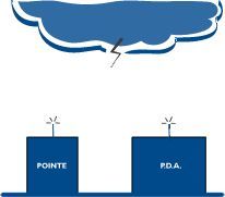
The sooner the rising discharge (upward leader) leaves the lightning rod to move toward the cloud, the sooner it will move closer to the downward leader and the greater the chances of the two making contact before other rising discharges from nearby high points. It can be seen, then, that it is the start point of the first upward leader which determines the point of impact of the lightning on the ground. An early streamer emission lightning rod is designed to provide optimal conditions for the formation of this rising discharge.
For this the following conditions are necessary :
- The presence of primary electrons at the top of the rod : these electrons, given off in the form of plasma, encourage the start-up of the rising discharge.
- Onised plasma being formed at the right moment when lightning is about to strike, in other words, in phase with the rising electric field at ground level.
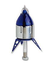
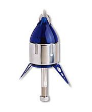
Prevectron® 2 features
In an intense electrical field, the lower set of sensors charges the ionization device with electrical energy and, when the lightning strikes, the upper set of electrodes generate sparks allowing an upward leader to form and intercept and channel the current down to earth through the central tip.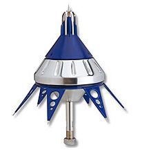
- central pickup tip made of electronytic copper or stainless steel passes through the lightning conductor creating an uninterrupted path to earth for the lightning to flow down
- A stainless steel waterproof housing, connected to earth
- An upper set of spark-generating electrodes
- An electrical triggering device, shielded in its protective housing.
- A lower set of sensors for absorbing ambient energy.
Key benefits of Prevectron® 2
The skills of INDELEC’s engineers, the variety of tests carried out in both high-voltage laboratories and real-life lightning conditions, and the experience gained from the thousands of PREVECTRON®2 installations around the world, have allowed us to develop a complete range of lightning conductors offering a host of key benefits :
- 5-model range offering customized solutions for each project (easthetic constraints, required protection area, etc.)
- Fully autonomous operation
- Total reliability, even in extreme climatic conditions
- Proven, robust design able to withstand multiple lightning strikes
- Lightning conductor only becomes active when electrical field intensity rises (lightning discharge likely), the PREVECTRON®2 presents no danger to the site
- Straightforward installation & maintenance using tools specially developed by INDELEC, including protection calculation software, strike counter and PREVECTRON® tester
- High-voltage laboratory test results available on request
- Real-life test results & scientific reports available on request
- Ultra-safe capture tip thanks to full electrical continuity between the tip and the earth point
- ISO 9001-2000 manufacturing process (certificate #116884)
Prevectron® 2 features
Five Prevectron2® models are available with the latest technical developments : central pickup rod and upper electrodes made of copper with chromium plating, new blue translucide cap including upper electrode insulation device and new blue coating of stainless steel lower electrodes.
Millenium Version : This latest version has been specifically developed to endure the most severe climatic conditions (humidity, heat).
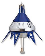
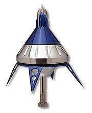
Diam. 185 mm - H = 385 mm Diam. 185 mm - H = 385 mm Diam. 185 mm - H = 385 mm

Diam. 100 mm - H = 330 mm Diam. 100 mm - H = 330 mm
Protection radius
A Prevectron®2 lightning conductor is protection radius Rp, is calculated according to the NF C 17-102 standard formula (July 95). It is dependent ona number of parameters :
- The Prevectron® is trigger advance T (see test summaries on the Prevectron® in high-voltage laboratory) wich allows ΔT to be calculated using the formula : ΔL (m) = ΔT(µs)
- Protection level I, II, or III is selected for the installation according to the risk of being struck by lightning. (NF C 17-102, Annex B)
- The true height of the lightning conductor above the surface to be protected : h
| h (m) | 2 | 3 | 4 | 5 | 10 |
|---|---|---|---|---|---|
| S 6.60 | 31 | 47 | 63 | 79 | 79 |
| S 4.50 | 27 | 41 | 55 | 68 | 69 |
| S 3.40 | 23 | 35 | 46 | 58 | 59 |
| TS 3.40 | 23 | 35 | 46 | 58 | 59 |
| TS 2.25 | 17 | 24 | 34 | 42 | 44 |
| h (m) | 2 | 3 | 4 | 5 | 10 |
|---|---|---|---|---|---|
| S 6.60 | 34 | 52 | 68 | 86 | 88 |
| S 4.50 | 30 | 45 | 60 | 76 | 77 |
| S 3.40 | 26 | 39 | 52 | 65 | 67 |
| TS 3.40 | 26 | 39 | 52 | 65 | 67 |
| TS 2.25 | 19 | 29 | 39 | 49 | 51 |
| h (m) | 2 | 3 | 4 | 5 | 10 |
|---|---|---|---|---|---|
| S 6.60 | 39 | 58 | 78 | 97 | 99 |
| S 4.50 | 34 | 52 | 69 | 86 | 88 |
| S 3.40 | 30 | 45 | 60 | 75 | 77 |
| TS 3.40 | 30 | 45 | 60 | 75 | 77 |
| TS 2.25 | 23 | 34 | 46 | 57 | 61 |
| h (m) | 2 | 3 | 4 | 5 | 10 |
|---|---|---|---|---|---|
| S 6.60 | 43 | 64 | 85 | 107 | 109 |
| S 4.50 | 38 | 57 | 76 | 95 | 98 |
| S 3.40 | 33 | 50 | 67 | 84 | 87 |
| TS 3.40 | 33 | 50 | 67 | 84 | 87 |
| TS 2.25 | 26 | 39 | 52 | 65 | 69 |
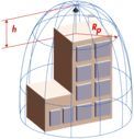
Rp = √( h(2D-h) + ΔL (2D+ ΔL) ) where h>5m. Where h<5m, see tables up.
D = 20, 45 or 60 depending on the level of protection required.
h = true height (in metres) of the PREVECTRON® above the surface to be protected.
ΔL = 106ΔT